UML Class Diagrams: Diagramming Guidelines
- Explore domain concepts in the form of a domain model
- Analyze requirements in the form of a conceptual/analysis model
- Depict the detailed design of object-oriented or object-based software
A class model is comprised of one or more class diagrams and the supporting specifications that describe model elements including classes, relationships between classes, and interfaces. There are guidelines for:
1. General Guidelines
Because class diagrams are used for a variety of purposes – from understanding requirements to describing your detailed design – you will need to apply a different style in each circumstance. This section describes style guidelines pertaining to different types of class diagrams.
Figure 1. Analysis and design versions of a class.

Figure 2. Modeling association classes.

- Identify Responsibilities on Domain Class Diagrams.
- Indicate Visibility Only On Design Models.
- Indicate Language-Dependent Visibility With Property Strings.
- Indicate Types Only On Design Models.
- Indicate Types On Analysis Models Only When The Type is an Actual Requirement.
- Design Class Diagrams Should Reflect Language Naming Conventions. In Figure 1 you see that the design version of the Order class uses names that conform to common Java programming conventions such as placementDate and calculateTaxes().
- Model Association Classes On Analysis Diagrams. Figure 2 shows that association classes are depicted as class attached via a dashed line to an association – the association line, the class, and the dashed line are considered one symbol in the UML.
- Do Not Name Associations That Have Association Classes.
- Center The Dashed Line of an Association Class.
2. Class Style Guidelines
A class is effectively a template from which objects are created (instantiated).Although in the real world Doug, Wayne, John, and Bill are all student objects we would model the class Student instead. Classes define attributes, information that is pertinent to their instances, and operations, functionality that the objects support. Classes will also realize interfaces (more on this later). Note that you may need to soften some of the naming guidelines to reflect your implementation language or software purchased from a third-party vendor.
Figure 3. The OrderItem class with and without scaffolding code.
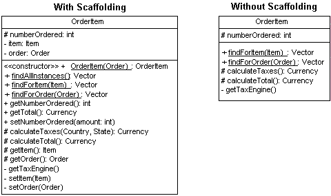
Figure 4. Indicating the exceptions thrown by an operation.
+ findAllInstances(): Vector {exceptions=NetworkFailure, DatabaseError}
- Use Common Terminology for Names
- Prefer Complete Singular Nouns for Class Names
- Name Operations with a Strong Verb
- Name Attributes With a Domain-Based Noun
- Do Not Model Scaffolding Code. Scaffolding code refers to the attributes and operations required to implement basic functionality within your classes, such as the code required to implement relationships with other classes. Figure 3 depicts the difference between the OrderItem class without scaffolding code and with it.
- Never Show Classes With Just Two Compartments
- Label Uncommon Class Compartments
- Include an Ellipsis ( . . . ) At The End of Incomplete Lists
- List Static Operations/Attributes Before Instance Operations/Attributes
- List Operations/Attributes in Decreasing Visibility
- For Parameters That Are Objects, Only List Their Type
- Develop Consistent Method Signatures
- Avoid Stereotypes Implied By Language Naming Conventions
- Indicate Exceptions In An Operation’s Property String. Exceptions can be indicated with a UML property string, an example of which is shown in Figure 4.
3. UML Class Diagrams: Interfaces
An interface is a collection of operation signature and/or attribute definitions that ideally defines a cohesive set of behaviors. Interfaces are implemented, “realized” in UML parlance, by classes and components – to realize an interface a class or component must implement the operations and attributes defined by the interface. Any given class or component may implement zero or more interfaces and one or more classes or components can implement the same interface.
Figure 5. Interfaces on UML class diagrams.

- Interface Definitions Must Reflect Implementation Language Constraints. In Figure 5 you see that a standard class box has been used to define the interface PersistentObject (note the use of the <> stereotype).
- Name Interfaces According To Language Naming Conventions
- Apply “Lollipop” Notation To Indicate That A Class Realizes an Interface
- Define Interfaces Separately From Your Classes
- Do Not Model the Operations and Attributes of an Interface in Your Classes. In Figure 5 you’ll notice that the Shipment class does not include the attributes or operations defined by the two interfaces that it realizes.
- Consider an Interface to Be a Contract
4. UML Class Diagrams: Relationship Guidelines
For ease of discussion the term relationships shall include all UML concepts such as associations, aggregation, composition, dependencies, inheritance, and realizations – in other words, if it’s a line on a UML class diagram we’ll consider it a relationship.
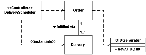
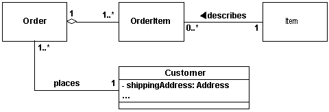
Figure 8. Professors and seminars.

Figure 9. Modeling people at a university.

- Model Relationships Horizontally
- Collaboration Indicates Need for a Relationship
- Model a Dependency When The Relationship is Transitory
- Depict Similar Relationships Involving A Common Class As A Tree. In Figure 6 you see that both Delivery and Order have a dependency on OIDGenerator. Note how the two dependencies are drawn in combination in “tree configuration”, instead of as two separate lines, to reduce clutter in the diagram.
- Always Indicate the Multiplicity
- Avoid a Multiplicity of “*”
- Replace Relationships By Indicating Attribute Types. In Figure 7 you see that Customer has a shippingAddress attribute of type Address – part of the scaffolding code to maintain the association between customer objects and address objects.
- Do Not Model Implied Relationships
- Do Not Model Every Single Dependency
- Center Names on Associations
- Write Concise Association Names In Active Voice
- Indicate Directionality To Clarify An Association Name
- Name Unidirectional Associations In The Same Direction
- Word Association Names Left-To-Right
- Indicate Role Names When Multiple Associations Between Two Classes Exist
- Indicate Role Names on Recursive Associations
- Make Associations Bi-Directional Only When Collaboration Occurs In Both Directions. The lives at association of Figure 9 is uni-directional.
- Redraw Inherited Associations Only When Something Changes
- Question Multiplicities Involving Minimums And Maximums
6. UML Class Diagrams: Inheritance Guidelines
Inheritance models “is a” and “is like” relationships, enabling you to easily reuse existing data and code. When “A” inherits from “B” we say that “A” is the subclass of “B” and that “B” is the superclass of “A.”Furthermore, we say that we have “pure inheritance” when “A” inherits all of the attributes and methods of “B.” The UML modeling notation for inheritance is a line with a closed arrowhead pointing from the subclass to the superclass.
- Apply the Sentence Rule For Inheritance
- Place Subclasses Below Superclasses
- Beware of Data-Based Inheritance
- A Subclass Should Inherit Everything
7. UML Class Diagrams: Aggregation and Composition Guidelines
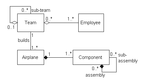
Sometimes an object is made up of other objects. For example, an airplane is made up of a fuselage, wings, engines, landing gear, flaps, and so on.A delivery shipment contains one or more packages. A team consists of two or more employees. These are all examples of the concept of aggregation, which represents “is part of” relationships.An engine is part of a plane, a package is part of a shipment, and an employee is part of a team.Aggregation is a specialization of association, specifying a whole-part relationship between two objects.Composition is a stronger form of aggregation where the whole and parts have coincident lifetimes, and it is very common for the whole to manage the lifecycle of its parts. From a stylistic point of view, because aggregation and composition are both specializations of association the guidelines for associations apply.
Figure 10. Examples of aggregation and composition.
- Apply the Sentence Rule for Aggregation
- You Should Be Interested In Both The Whole And The Part
- Depict the Whole to the Left of the Part
- Apply Composition to Aggregates of Physical Items
- Apply Composition When the Parts Share The Persistence Lifecycle With the Whole
- Don’t Worry About Getting the Diamonds Right


