
UML Frames: Diagramming Style Guidelines

Figure 2. Modeling alternate courses of logic.
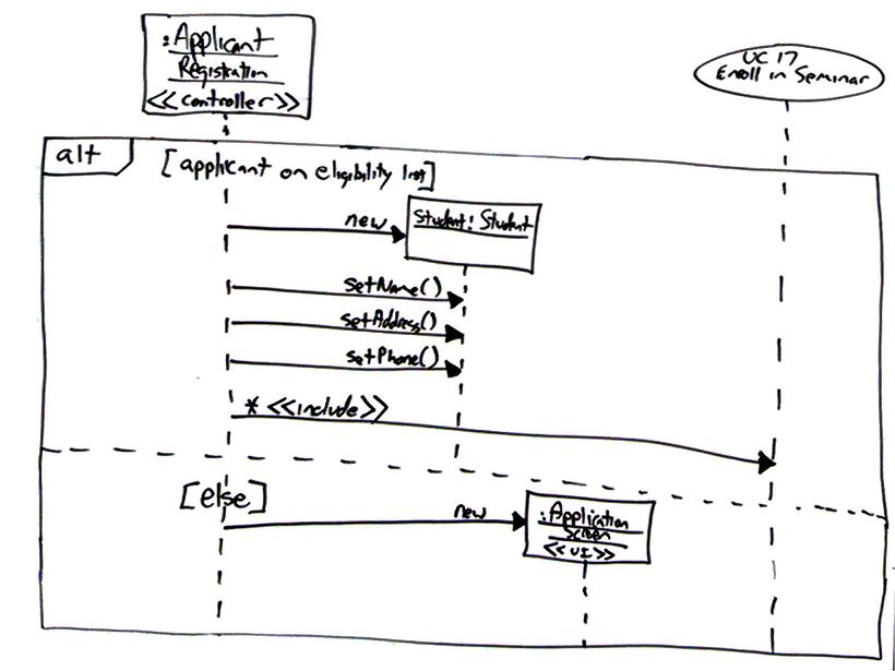
Figure 3. The internals of the seminar component.

- Avoid Diagram Frames. The Batch Transcript Printing diagram frame of Figure 1 adds a significant amount of visual clutter in the process.
- Use Interaction Occurrences Over Part Decompositions. There are two references to logic external to Figure 1: the TranscriptBatch object includes a reference to PrintRun and there is a combined fragment referencing the SharedServices.print() method. The style of the first reference is called a part decomposition and the second an interaction occurrence.
- Fully Specify Operation Names in References.
- Depict One Interface Per Port. Ports are connection points between a classifier and its environment. Ports are depicted on the side of frames as small rectangles.
- Depict One Port Per Realizing Class. See also UML interface style guidelines.
- Deemphasize Frame Borders. In Figure 1 you see that the frame border is lighter than the lines around it.
- Apply Standard Labels to Descriptors. Table 1 summarizes common labels for diagram frames and Table 2 the common labels for combined fragments.
Table 1. Diagram frame labels.
| Label | Usage |
| Component | The frame depicts the internal design of a component. |
| Package | The frame depicts the internal organization of a package, often using a UML class diagram or a UML use case diagram. |
| sd | Indicates that the frame contains an interaction diagram, usually a UML sequence diagram although UML communication diagrams are also common options. |
| Use Case | The frame depicts the logic of a use case, often as a UML activity diagram or a UML interaction overview diagram. |
Table 2. Combined fragment labels.
| Label | Usage |
| alt | Indicates several alternatives, only one of which will be taken, separated by dashed lines. Used to model if and switch statements. See the example in Figure 2. |
| assert | Indicates that the fragment models an assertion. |
| criticalRegion | Indicates that the fragment must be treated as atomic and cannot be interleaved with other event occurrences. Often used within a par frame (Douglass 2004). |
| loop | Models logic which will be potentially repeated several times. |
| opt | Models optional logic depending on the run-time evaluation of a guard. |
| par | Indicates several fragments of logic, separated by dashed lines, all of which will run in parallel. |
| ref | References another diagram or a method definition. |