UML Use Case Diagrams: Diagramming Guidelines
- Provide an overview of all or part of the usage requirements for a system or organization in the form of an essential model or a business model
- Communicate the scope of a development initiative
- Model your analysis of your usage requirements in the form of a system use case model>
A use case model is comprised of one or more use case diagrams and any supporting documentation such as use case specifications and actor definitions. Within most use case models the use case specifications tend to be the primary artifact with use case diagrams filling a supporting role as the “glue” that keeps your requirements model together. Use case models should be developed from the point of view of your stakeholders and not from the (often technical) point of view of developers. There are guidelines for:
1. Use Cases
A use case describes a sequence of actions that provide a measurable value to an actor. A use case is drawn as a horizontal ellipse on a UML use case diagram, as you see in Figure 1.
- Use Case Names Begin With a Strong Verb
- Name Use Cases Using Domain Terminology
- Place Your Primary Use Cases In The Top-Left Corner Of The Diagram
- Imply Timing Considerations By Stacking Use Cases. As you see in Figure 1, the use cases that typically occur first are shown above those that appear later.
Figure 1. Implying timing considerations between use cases.

2. Actors
An actor is a person, organization, or external system that plays a role in one or more interactions with your system (actors are typically drawn as stick figures on UML Use Case diagrams).

- Place Your Primary Actor(S) In The Top-Left Corner Of The Diagram
- Draw Actors To The Outside Of A Use Case Diagram
- Name Actors With Singular, Business-Relevant Nouns
- Associate Each Actor With One Or More Use Cases
- Actors Model Roles, Not Positions
- Use <> to Indicate System Actors
- Actors Don’t Interact With One Another
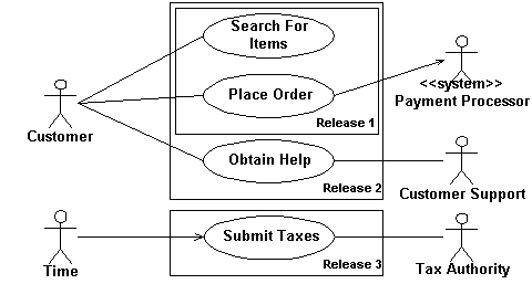
- Introduce an Actor Called “Time” to Initiate Scheduled Events
3. Relationships
There are several types of relationships that may appear on a use case diagram:
- An association between an actor and a use case
- An association between two use cases
- A generalization between two actors
- A generalization between two use cases
Associations are depicted as lines connecting two modeling elements with an optional open-headed arrowhead on one end of the line indicating the direction of the initial invocation of the relationship. Generalizations are depicted as a close-headed arrow with the arrow pointing towards the more general modeling element.
Figure 3. Enrolling students in a university.

- Indicate An Association Between An Actor And A Use Case If The Actor Appears Within The Use Case Logic
- Avoid Arrowheads On Actor-Use Case Relationships
- Apply <> When You Know Exactly When To Invoke The Use Case
- Apply <> When A Use Case May Be Invoked Across Several Use Case Steps
- Introduce <> associations sparingly
- Generalize Use Cases When a Single Condition Results In Significantly New Business Logic
- Do Not Apply <>, <>, or <>
- Avoid More Than Two Levels Of Use Case Associations
- Place An Included Use Case To The Right Of The Invoking Use Case
- Place An Extending Use Case Below The Parent Use Case
- Apply the “Is Like” Rule to Use Case Generalization
- Place an Inheriting Use Case Below The Base Use Case
- Apply the “Is Like” Rule to Actor Inheritance
- Place an Inheriting Actor Below the Parent Actor
4. System Boundary Boxes
The rectangle around the use cases is called the system boundary box and as the name suggests it indicates the scope of your system – the use cases inside the rectangle represent the functionality that you intend to implement.
- Indicate Release Scope with a System Boundary Box. In Figure 2 you see that three system boundary boxes are included, each of which has a label indicating which release the various use cases have been assigned to.
- Avoid Meaningless System Boundary Boxes.


